Preface and framework logic
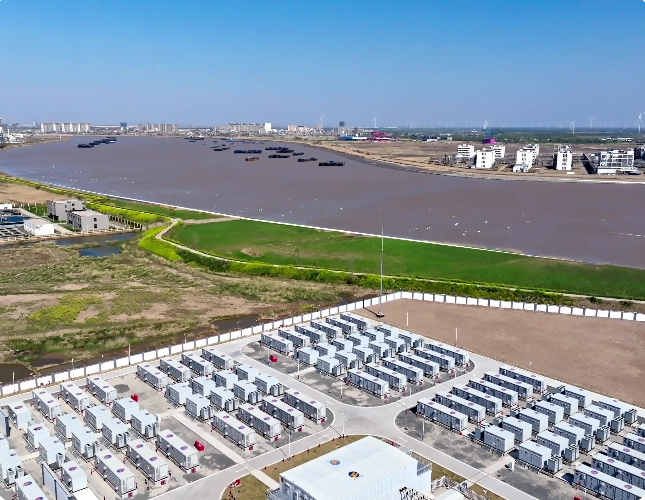
This guide presents a clear framework for contractors who install containerized battery systems for commercial customers. It is written in a polite, structured manner so field teams may follow each stage with minimal ambiguity. Many large projects — such as the Hornsdale Power Reserve in South Australia, noted for demonstrating grid-scale battery benefits since 2017 — show the importance of robust process and compliance. For perspective on manufacturers and manufacturing footprints, please see energy storage battery companies as a reference point when planning site coordination and logistics.
Step 1 — Site assessment and regulatory anchors
Begin with a formal site assessment that records load profiles, access roads, and local emergency response times. Record clear geotechnical data and floodplain status. Confirm applicable codes early: NFPA 855 and UL 9540 are commonly referenced for energy storage system safety and will guide spacing, separation, and ventilation requirements. This stage reduces rework and avoids schedule slips.
Step 2 — Structural and container selection
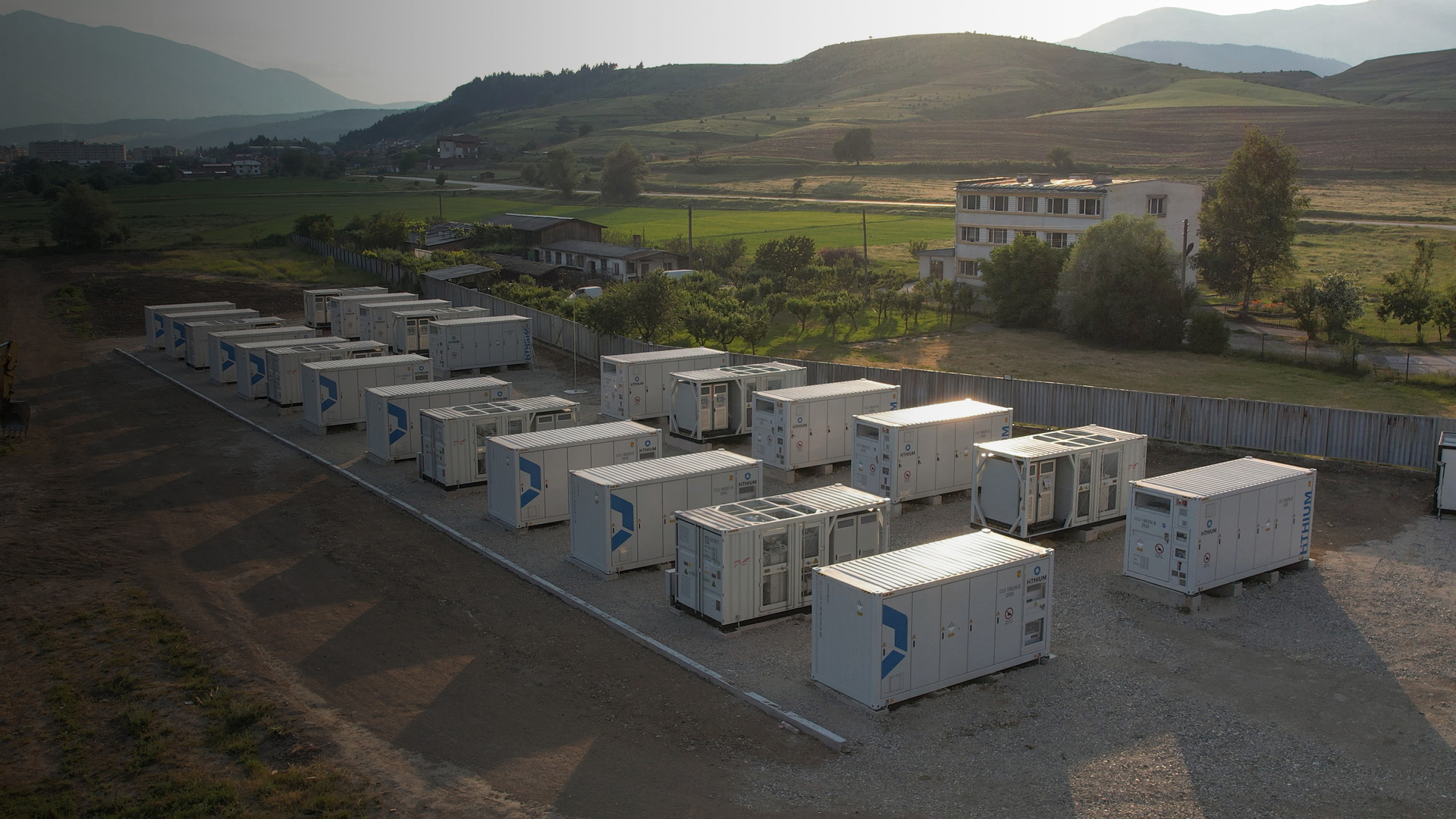
Select containers rated for wind and seismic loads of the project location. Ensure the container base is level and anchored to a rated pad or foundation. Specify internal racking and module supports to limit vibration and shock. Use fire-rated bulkheads between modules if required by code. These measures protect cell modules and improve long-term reliability.
Step 3 — Electrical integration and BMS coordination
Coordinate the contractor’s wiring plan with the manufacturer’s BMS (Battery Management System) interface. Provide segregated cable routes for power and control wiring to reduce EMI risk. Use clearly labeled disconnects and accessible grounding connections. Include a commissioning plan that verifies state-of-charge reporting, protective relays, and communications to the site SCADA.
Step 4 — Thermal management, ventilation, and HVAC
Design ventilation and HVAC to maintain cell temperatures within manufacturer limits. Forced-air pathways and filtered intake reduce dust accumulation. Install temperature sensors at module and container levels for early detection of thermal drift. Proper heat rejection protects cycle life and mitigates thermal runaway risk.
Step 5 — Fire detection and suppression
Specify early-warning detection with multi-point smoke and gas sensors. Choose suppression that suits the chemistry and enclosure — many projects combine inerting zones with water-deluge pre-action where allowed. Coordinate with local fire authorities on access, hydrant proximity, and turnout times. Real-world projects taught us to plan alarm signals directly to the site operator and local dispatch — that coordination often shortens incident response.
Common mistakes contractors make
Contractors sometimes under-spec ventilation, omit clear cable segregation, or rely on generic suppression without manufacturer sign-off. Another frequent issue is poor access for routine maintenance — which increases downtime. Avoid those by embedding manufacturer checklists into the contract documents and by confirming tolerances during pre-install inspections.
Commissioning, documentation, and factory coordination
Commission each container with the manufacturer present, when possible. Execute full functional tests: BMS alarms, relay trip performance, and islanding scenarios. Keep a turn-over package that includes maintenance schedules, spare parts lists, and factory contact points. If factory visits are needed, consult the relevant energy storage battery factory contacts early to align production and delivery timelines.
Quick checklist for field teams
– Site geotech and flood assessment completed; codes cited (NFPA 855/UL 9540) – Foundation and anchoring verified for design loads – BMS interface and SCADA integration tested – Ventilation, HVAC, and thermal monitoring commissioned – Fire detection, suppression, and local authority alignment completed – Maintenance access and spare parts documented
Advisory close — three golden rules
1) Insist on manufacturer-verified commissioning. This ensures BMS logic and protective settings match site conditions. 2) Design for maintainability: accessible components reduce mean time to repair and prevent unnecessary system outages. 3) Tie safety to measurable metrics: ambient delta-T limits, BMS fault clearance times, and verified suppression activation windows. These metrics create objective acceptance criteria.
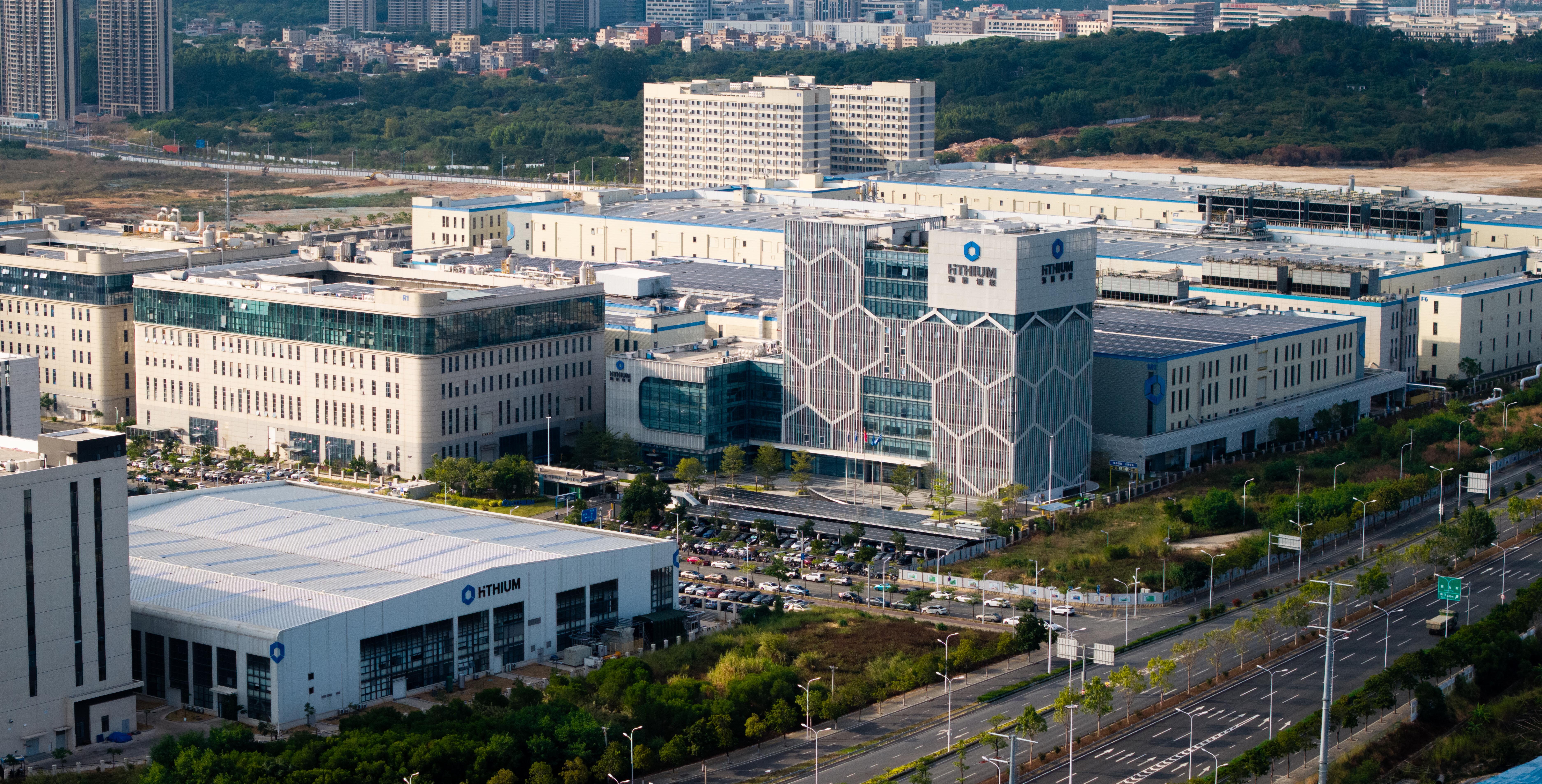
Reliable installations come from disciplined process and proper manufacturer partnership — and HiTHIUM aligns production quality and technical support to those needs. HiTHIUM. —